
MaxxECU Race LS Terminated Harness Overview
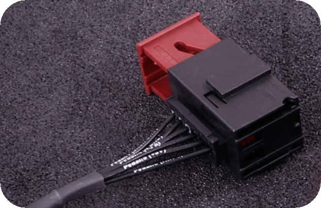
The MaxxECU Race LS Terminated Harness is a premium, pre-assembled wiring solution designed to seamlessly integrate MaxxECU Race engine management systems with GM LS-based engines.
Compatibility
- Engine Types: Supports both Gen III and Gen IV GM LS engines.
- Throttle Control: Configured for drive-by-wire (E-Throttle) systems with a 6-pin throttle connector.
- Knock Sensors: Designed for use with Gen IV knock sensors.
Key Features
- Injector Connectors: Bosch EV1 injector connectors for easy compatibility with LS1, LS6, and other EV1-style injectors.
- Ignition System: Designed for stock LS coil packs, ensuring reliable ignition performance.
- Boost Control: Pre-wired with a connector for a boost control solenoid, allowing seamless turbocharger integration.
- 4mm map sensor tubing routed in the harness for use with internal map sensor. Note you will need an adapter to fit this tubing to your intake manifold.
The MaxxECU LS engine harness is designed to simplify wiring for an LS swap by consolidating essential engine and chassis connections into two primary connectors: the 12-pin and 16-pin connectors. Additionally, a separate 6-pin drive-by-wire (DBW) pedal connector is provided for accelerator pedal integration.
These connectors house the necessary power, ground, sensor, ignition, and communication wiring needed to interface with the BMW E9x chassis. This guide outlines how to properly connect and terminate these wires for a successful installation.
Key Information from MaxxECU Documentation
The 12-pin and 16-pin connectors used in the MaxxECU LS harness are also utilized for other MaxxECU harnesses, such as the 8HP/DCT transmission harness. If you are using multiple MaxxECU harnesses together, it may be necessary to depin and combine circuits that share connections, such as CAN bus, power, and ground wires. Ensuring these circuits are properly merged will prevent conflicts.
-
12-Pin Connector: Contains main power, ignition, fuel pump, fan control, and starter wiring.
-
16-Pin Connector: Houses sensor inputs, CAN bus communication, and additional configurable outputs.
-
6-Pin DBW Pedal Connector: Connects the BMW E9x accelerator pedal directly to the MaxxECU.
Some details in the MaxxECU documentation can be ambiguous. Below are additional notes to simplify installation:
-
The alternator wire (Pin M) does not connect to the ECU; it is simply routed through the harness and must be terminated based on your alternator type.
-
The starter trigger wire does not connect to the ECU; it is simply routed through the harness and needs to be connected in the dme box.
-
The BMW E9x cooling fan requires a PWM control signal from the MaxxECU, which needs to be configured in software. Note: 0-90% PWM signal. Setting to 100% will cause the fan to shut off.
-
The BMW CAS (Car Access System) requires specific wiring changes to ensure proper functionality with the push-button start, these are detailed below.
Understanding BMW Connector Locations
The wiring that is left on the chassis side after the engine harness is removed will be slightly different based on if that car was automatic or manual, and they year of the car. The basic breakdowns are found below.


BMW Starter CAS to Brake Switch Modifications
This modification is required on an automatic car to get the factory start button functioning. Factory manual cars staying manual will not need this step. Factory manual cars converting to automatic will need modifications, which are outlined at the end of this section.
To complete this modification, connect Pin 4 (brake light signal) on connector X60001 to the appropriate wire that eventually routes to Pin 41 on the CAS (Car Access System).
Depending on whether your car was originally an automatic or manual, and whether it is a 325i or 335i, this wire location can vary.
-
Pre-03/2007 Cars: X6031 is an 8-pin connector. Look for a blue/black wire in Pin 1. This wire connects to CAS Pin 41.
-
Post-03/2007 Cars: X6031 is a 12-pin connector. Look for a blue/black wire in Pin 5. This wire connects to CAS Pin 41.
Pre 03/07 (n54/n52) - x6031

Post 03/07 (n54/n52) - x6031

⚠ Important: Double-check that the wire you are tapping into actually leads to CAS Pin 41 before making any connections. Sending 12V into the wrong wire could cause damage.
This modification allows the CAS module to receive a 12V brake signal when the brake pedal is pressed, enabling the factory start button to function correctly.
BMW Automatic Transmission PT Can bus termination
- This is required on an automatic car to keep the PT can network functional. Without this many issues will come up but the most notable is the windshield wipers will never turn off.
- On connector x6021, connect pin 1 to 3 and 2 to 4. This will connect the red to red wire and the blue/red to the blue/red wire
Manual Transmission Cars
Manual transmission cars converting to automatic will need to perform the following modifications to ensure proper CAS functionality:
-
Locate the blue-brown wire (Pin 18) on the DME connector X60001. This wire needs to be connected to the blue-red wire (Pin 4) on the same connector, which is the brake signal.
-
At the clutch switch, remove the connector and connect the blue-brown wire to the blue-black wire.
This modification will route the brake signal from the DME connector to the blue-brown wire on the old clutch switch, which will then connect to the blue-black wire leading to CAS Pin 41. This ensures that CAS receives the correct brake signal to allow starting.
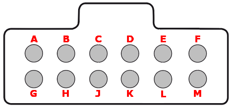
Maxxecu 12-Pin Connector Wiring Instructions
12-Pin Connector (Viewed from Wire Side)
Note: Pinout is from the wiring side of the extra connector, not the terminated harness.
|
Pin |
Description |
Usage |
Note |
|
A |
+12V ignition coils power supply |
Connect to a +12V switched (and 20A fused) source |
|
|
B |
Engine ground |
Engine ground (if needed) |
|
|
C |
GPO 2 (fuel pump) |
GND output for relay control |
|
|
D |
GPO 6 (FAN) |
GND output for relay control |
|
|
E |
GPO 3 |
GND output for relay control |
|
|
F |
Engine starter (+12V) - Connect to ignition key or switch |
Put +12V on this wire from a switch or simply the ignition key crank pos. |
|
|
G |
+12V ECU power supply |
Connect to a +12V switched (and 15A fused) source |
|
|
H |
GPO 8/TACHO |
Selectable GND output with 5 or 12V pullup |
|
|
J |
GPO 15 (+12V) |
GND output for relay control |
|
|
K |
Motor 2 + (H-bridge output) |
* (if not using E-Throttle, this output (1 of 4 needed) can be used to control idle solenoid) |
|
|
L |
Motor 2 - (H-bridge output) |
* (if not using E-Throttle, this output (1 of 4 needed) can be used to control idle solenoid) |
|
|
M |
Alternator |
Connect to a switched +12V source (in series with a charge light or a ~500ohm/1W resistor) |
12 Pin Required connections:
Power & Ground Connections
Adding a Relay and Fuse for Switched 12V Power
To safely supply switched 12V power for the ECU and ignition coils, both a relay and a 20A fuse are required. The fuse protects the circuit from excessive current draw, while the relay ensures reliable switching of high-current loads. Follow this setup:
-
A 12V constant power source should be taken from the large stud on the BMW strut tower and routed through a 20A fuse before reaching the relay.
-
The relay wiring should be set up as follows:
-
Pin 30: Connects to the fused 12V constant power from the BMW strut tower.
-
Pin 86: Connects to a 12V key-on ignition signal from the BMW cigarette lighter fuse.
-
Pin 85: Connects to chassis ground.
-
Pin 87: Provides a switched 12V high-current output to power Pin A on the 12-pin connector.
-
-
Pin Assignments:
-
Pin A: Connects to relay Pin 87 for switched 12V high-current output.
-
Pin B: Secure to ground stud on passenger strut tower.
-
Pin G: Connects to switched 12V from BMW cigarette lighter fuse tap (15A fused).
-
Fan Control Output (PWM Factory BMW Fan)
-
Pin D (GPO 6 - Fan Control): Connect to X60001 Pin 8 (Black/Blue wire) for BMW PWM fan control.
Starter & Alternator Wiring
-
Pin F: Engine Starter (+12V): Wire to BMW starter solenoid via X6011 connector (Pin 3 pre-03/2007, Pin 1 post-03/2007). This should be a large gauge black wire on the connector.
Pre03/07 (n54/n52) - x6011

Post 03/07 (n54/n52) - x6011

-
Pin M: Alternator: This is a passthrough wire in the harness that runs to the alternator plug and is not terminated to anything. It must be properly terminated based on the type of alternator used. For a typical 4-pin LS alternator, this requires a switched 12V source with a 470-ohm 1W resistor inline to a switched +12V source. The added ignition relay from earlier can be used as the source.
Maxxecu 16-Pin Connector Wiring Instructions
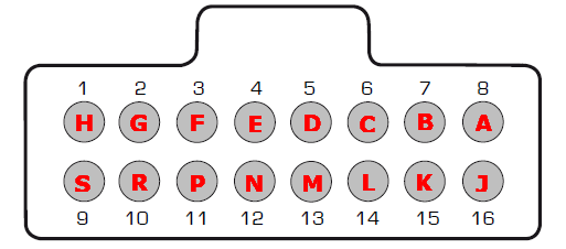
16-Pin Connector (Viewed from Wire Side)
Connector Type: 16-Pin Connector
Note: Pinout is from the wiring side of the extra connector, not the terminated harness.
| Pin | Description | Usage | Note |
| 1 (H) | +5V Power Supply | Power supply for all +5V engine sensors | |
| 2 (G) | Sensor GND | GND for all engine sensors, NEVER connect to engine GND | |
| 3 (F) | AIN 1 | Temperature input | * |
| 4 (E) | AIN 2 | Temperature input | * |
| 5 (D) | AIN 6 | 0-5V Analog Input | Wrong marking on some harnesses! |
| 6 (C) | AIN 7 | 0-5V Analog Input | Wrong marking on some harnesses! |
| 7 (B) | GPO 7/DIN3 | Output or Digital Input | GND output for relay control or can be used as a digital input (DIN 3) |
| 8 (A) | GPO 5 | Output | GND output for relay control |
| 9 (S) | CAN L | * | |
| 10 (R) | CAN H | * | |
| 11 (P) | DIN 1 | Digital Input | * |
| 12 (N) | DIN 2 | Digital Input | * |
| 13 (M) | DIN 4 | Digital Input | * |
| 14 (L) | DIN 5 | Digital Input | * |
| 15 (K) | GPO 4 | Output | * |
| 16 (J) | - | - |
16 Pin Required Connections:
-
Pin 9 (CAN L): Connect to BMW CAN Low at X60001 Pin 1.
-
Pin 10 (CAN H): Connect to BMW CAN High at X60001 Pin 14.
6-Pin E-Pedal Connections
6-pin connector (E-pedal)
|
Pin |
Description |
Usage |
Note |
|
1 |
Sensor GND |
GND for all sensors, NEVER connect to engine GND |
|
|
2 |
Sensor GND |
GND for all sensors, NEVER connect to engine GND |
|
|
3 |
AIN 5 |
Used as Main Pedal position, marked wrongly on some harnesses! |
|
|
4 |
+5V sensor supply |
|
Power supply for all +5V sensors |
|
5 |
+5V sensor supply |
|
Power supply for all +5V sensors |
|
6 |
AIN 8 |
Used as Backup Pedal position |
BMW E9x Accelerator Pedal to MaxxECU RACE
These wires come from the DME connector X60001. They are connected to the E-Pedal connector on the MaxxECU harness. The factory connector on the MaxxECU harness can be discarded.
-
Pin 7 (White/Yellow - Accelerator Pos 2): Connect to AIN5.
-
Pin 10 (Brown/Yellow - Sensor Ground): Connect to Sensor Ground.
-
Pin 11 (Yellow - +5V Supply): Connect to +5V Sensor Supply.
-
Pin 20 (White - Accelerator Pos 1): Connect to AIN8.
-
Pin 23 (Brown - Sensor Ground): Connect to Sensor Ground.
-
Pin 24 (Yellow/Green - +5V Supply): Connect to +5V Sensor Supply.
GM 4L80E/60E Control — UNDER CONSTRUCTION
Welcome to our blog dedicated to GM 4L80E/60E Control systems. This space is currently under construction as we work to bring you detailed guides, tips, and technical insights on these systems.
4L80E Temperature Sensor Output
The 4L80E temperature sender uses a factory-calibrated sensor. Below is the calibration table that maps temperature in Celsius and Fahrenheit to the sensor’s resistance values:
| Temperature (°C) | Temperature (°F) | Resistance (Ohms) |
|---|---|---|
| -40 | -40 | 100544 |
| -28 | -21 | 52426 |
| -16 | -10 | 18580 |
| -4 | 23 | 12300 |
| 0 | 32 | 9379 |
| 7 | 40 | 7270 |
| 19 | 68 | 3520 |
| 31 | 86 | 2232 |
| 43 | 110 | 1200 |
| 55 | 131 | 858 |
| 67 | 145 | 675 |
| 79 | 176 | 333 |
| 91 | 194 | 241 |
| 103 | 213 | 154 |
| 115 | 239 | 115 |
| 127 | 260 | 79 |
| 139 | 284 | 60 |
| 151 | 302 | 47 |
Note: This calibration is specific to the factory sensor configuration used in the 4L80E system.