
This is the chassis-side wiring for an LS or LT swap in the E9x/E8x, in one place. Pick your engine family and your ECU, and the page shows only the connections that apply to your combo. Everything here comes from our full guides, which stay linked at the bottom if you want the deep version.
Your donor chassis engine:
Your ECU:
Jump to a section:
- The DME Box
- MaxxECU Harness
- Key-On Power
- Constant 12V
- Ground
- Drive-By-Wire Pedal
- Cooling Fan
- Start Button and CAS
- Starter Solenoid
- PT CAN Termination
- Fuel Pump and EKP
- LT Fuel Sensors
- Air Conditioning
- Chassis CAN
- Trans Temp Sensor
- Pin Reference
- The Full Guides
The DME Box
Nearly all of the chassis wiring happens at the DME box in the engine bay. After the factory engine harness comes out, the connectors left behind are your interface to the car. What's left on the chassis side differs a little based on whether the car was automatic or manual and the model year, and the sections below call out those splits where they matter.


On N55 cars the DME lives under the intake manifold, not in the DME box. The box holds plastic dividers and a few relays and fuses.

Once those are out, four connectors remain, and X60001 is the only one whose wires you need: drive-by-wire, radiator fan, key-on power, and the CAN interface. The other pins on X60001 can be used if you want them, but they aren't required for the swap. If you want more room in the box, cut the unused connectors off and terminate the wires with heat shrink.

The N55 chassis walkthrough here comes from Evan Schulte's documented build, written up in full in the N55 notes.
On the ECU side, here's the GM E92's X1, X2, and X3 connector layout for reference:

The MaxxECU Terminated Harness
The LSe9x MaxxECU terminated harness consolidates the swap wiring into two main connectors plus a separate 6-pin drive-by-wire pedal connector. Pinouts for the 12-pin and 16-pin connectors are in the pin reference tables at the bottom of this page, and the 6-pin pedal pinout is in the drive-by-wire section.
- 12-pin connector: main power, ignition, fuel pump, fan control, and starter wiring
- 16-pin connector: sensor inputs, CAN bus, and additional configurable outputs
- 6-pin pedal connector: the BMW accelerator pedal
The harness is built for Gen III and Gen IV LS engines, drive-by-wire throttle with a 6-pin throttle connector, and Gen IV knock sensors, so plan on Gen IV style knock sensors if your engine is a Gen III. It uses Bosch EV1 injector connectors (LS1, LS6, and other EV1-style injectors), is built for stock LS coil packs, and comes pre-wired with a boost control solenoid connector. 4mm MAP sensor tubing is routed in the harness for the internal MAP sensor, and you'll need an adapter to fit that tubing to your intake manifold.
The 8HP/DCT transmission harness uses the same 12-pin and 16-pin connectors. If you run multiple MaxxECU harnesses together, you may need to depin and combine the circuits they share (CAN bus, power, and grounds) so they don't conflict.
Key-On Ignition Power
Every combo should use a fuse tap at the cigarette lighter fuse, fuse 8 or 30 depending on year (a few years put it elsewhere, so check your fuse card). It gives 12V in accessory mode and holds through cranking, key off gives nothing, and it doesn't fight the car's sleep logic.
Alternative: E90 connector X6011 pin 6, green/white. Check it with a test light, key on 12V, key off dead. This wire also wakes during the car's self checks and can cause battery drain, so we don't recommend it. The fuse tap is the better source.
The terminated harness does not include fuses or relays, so the power side is on you. To supply switched 12V for the ECU and ignition coils, add a relay and a 20A fuse. The fuse protects the circuit, the relay does the high-current switching:
- Take constant 12V from the large stud on the strut tower and route it through a 20A fuse to the relay.
- Wire the relay: pin 30 to that fused constant feed, pin 86 to the key-on signal from the cigarette lighter fuse tap, pin 85 to chassis ground, pin 87 out to harness Pin A.
- Harness side: Pin A (ignition coil power) comes from relay pin 87, Pin B goes to the ground stud on the passenger strut tower, and Pin G (ECU power) gets a 15A-fused switched 12V feed from the cigarette lighter fuse tap.
Run the key-on wire to the ignition input of your Gen V swap harness (X1-51 is the run/crank ignition input at the ECU). LT standalone swap harnesses typically have a built-in fuse and relay for ignition power, so check yours before adding another.
Do not use X60001 pin 8 (blue/red) as your key-on source. It fires short bursts of power when the car is locked, unlocked, or a door opens, and those stray pulses aren't good for an ECU long term. Here's the power region of the N55 X60001 connector:

X60001 pin 39 (green/yellow) has been used for the Holley red/white ignition wire on N55 cars.
Constant 12V Supply
Source constant 12V from the main jump terminal stud on the passenger strut tower. The large stud is unfused. The small stud is fused by a fusible link above the battery in the rear of the car, so if the small stud is dead, check that link. DO NOT use the small stud for starter or alternator power, it will blow the fuse.
N55 cars have a relay at the battery that cuts the factory DME power feed after a timeout, so don't reuse that feed for constant power. Take constant power from the battery itself or the jump stud, which don't go through that relay. The relay can be coded out, but skipping that feed is the fix.
Wire the Holley's main power directly to the battery. Powering it through the old DME feed means the relay timeout loses your tune and the TPS autoset, and the Holley manuals tell you to wire main power straight to the battery anyway.
Most LT swap harnesses put the main power ring terminal at the starter, though it varies by harness. At the ECU, X1-52, X1-70, and X1-73 are the constant battery feeds. Run a proper cable from the large jump stud if your harness needs a separate constant feed.
The N55 battery relay only switches the factory DME feed, so a harness main feed at the starter or the large jump stud doesn't go through it.
Ground
Ground from any of the main ground studs in the engine bay. Ground both the engine block and the alternator.
The LSe9x alternator bracket is powder coated and will not give the alternator a good ground on its own, so run a dedicated strap or sand the coating at the mount.
LT brackets that keep the factory aluminum alternator mount don't have a bracket ground issue.
If you're running a 1-wire alternator, the exciter wire just needs any 12V ignition signal with a 470 ohm resistor inline. The resistor matters, because without it you can burn out the alternator's voltage regulator.
The green fuel pump wire from the Holley harness is a good option for the exciter signal if you've replaced the EKP with a relay.
On the terminated harness, the alternator wire (Pin M on the 12-pin connector) is a passthrough: it runs to the alternator plug, does not connect to the ECU, and comes unterminated. Terminate it for your alternator. For a typical 4-pin LS alternator that means switched 12V with a 470 ohm 1W resistor inline, and the ignition relay from the key-on section works as the source.
Drive-By-Wire Pedal
The BMW pedal is drive-by-wire, six wires, and they come off the long grey DME connector X60001. Where they land depends on your ECU.
The pedal region of the N55 X60001 connector:

| BMW X60001 | Holley DBW Harness |
| Pin 7 - White/yellow | Blue - Pin B, TPS #2 |
| Pin 10 - Brown/yellow | Black - Pin A/D, sensor ground |
| Pin 11 - Yellow | Orange - Pin C/F, sensor 5V |
| Pin 20 - White | Yellow - Pin E, TPS #1 |
| Pin 23 - Brown | Black - Pin A/D, sensor ground |
| Pin 24 - Yellow/green | Orange - Pin C/F, sensor 5V |
The N55 pedal pins on X60001 differ from N52/N54 cars:
| BMW X60001 (N55) | Holley DBW Harness |
| Pin 14 - Blue (A_FWG1) | Yellow - Pin E, TPS #1 |
| Pin 15 - White/yellow (A_FWG2) | Blue - Pin B, TPS #2 |
| Pin 24 - Yellow/green (U_FWG2) | Orange - Pin C/F, sensor 5V |
| Pin 25 - Yellow (U_FWG1) | Orange - Pin C/F, sensor 5V |
| Pin 27 - Brown/green (M_FWG1) | Black - Pin A/D, sensor ground |
| Pin 28 - Brown (M_FWG2) | Black - Pin A/D, sensor ground |
The BMW pedal wires terminate into the 6-pin E-pedal connector on the MaxxECU harness. The factory pedal connector that comes on the harness can be discarded. The E-pedal connector pinout, viewed from the wire side:
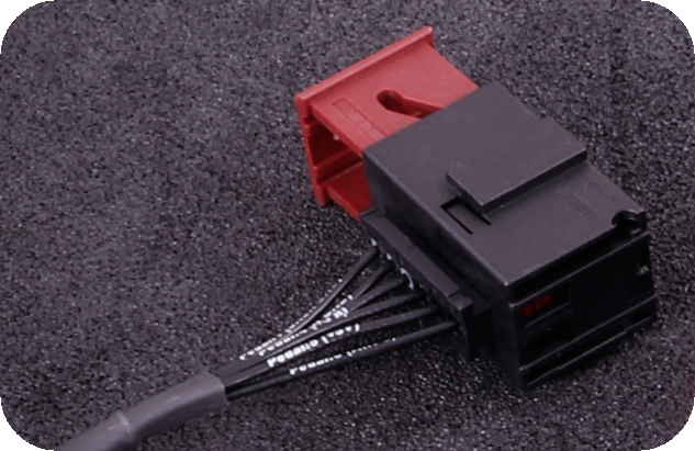
| Pin | Function | Note |
| 1 | Sensor ground | Ground for all sensors, NEVER connect to engine ground |
| 2 | Sensor ground | Ground for all sensors, NEVER connect to engine ground |
| 3 | AIN 5, 0-5V analog input | Main pedal position. Marked wrongly on some harnesses! |
| 4 | +5V sensor supply | Power supply for all 5V sensors |
| 5 | +5V sensor supply | Power supply for all 5V sensors |
| 6 | AIN 8, 0-5V analog input | Backup pedal position |
The six pedal wires from X60001 land on the E-pedal connector like this:
| BMW X60001 | MaxxECU E-pedal |
| Pin 7 - White/yellow (accelerator pos 2) | AIN 5 |
| Pin 10 - Brown/yellow | Sensor ground |
| Pin 11 - Yellow | +5V sensor supply |
| Pin 20 - White (accelerator pos 1) | AIN 8 |
| Pin 23 - Brown | Sensor ground |
| Pin 24 - Yellow/green | +5V sensor supply |
Cross-referenced from our N55 pinout and the MaxxECU pedal mapping, matching each wire by function:
| BMW X60001 (N55) | MaxxECU E-pedal | Function |
| Pin 14 - Blue (A_FWG1) | AIN 8 | Pedal signal 1 |
| Pin 15 - White/yellow (A_FWG2) | AIN 5 | Pedal signal 2 |
| Pin 24 - Yellow/green (U_FWG2) | +5V sensor supply | 5V supply |
| Pin 25 - Yellow (U_FWG1) | +5V sensor supply | 5V supply |
| Pin 27 - Brown/green (M_FWG1) | Sensor ground | Low reference |
| Pin 28 - Brown (M_FWG2) | Sensor ground | Low reference |
Verify the two pedal signals in MTune before first start, since the signal 1 / signal 2 split is the one place a functional cross-reference can land backwards.
The six pedal wires route to your harness's 6-pin pedal DBW connector, labelled A through F. That's where the actual connection happens; the X1 ECU pin numbers in the tables below are for diagnosis. Car/Corvette and truck harnesses share the same plug but swap pins A and C, and truck harnesses put the two 5V wires in the center positions C and D. Check which donor harness you have before pinning, then use the truck or car column below. There's also a pedal wiring video covering this connector.

| BMW X60001 | Truck pin | Car pin | GM E92 X1 (diagnosis) | Function |
| Pin 20 - White | E | E | X1-15 | Pedal signal 1 |
| Pin 7 - White/yellow | B | B | X1-34 | Pedal signal 2 |
| Pin 11 - Yellow | C | A | X1-14 or X1-33 | 5V supply |
| Pin 24 - Yellow/green | D | D | X1-33 or X1-14 | 5V supply |
| Pin 10 - Brown/yellow | A | C | X1-30 | Low reference |
| Pin 23 - Brown | F | F | X1-53 | Low reference 2 |
The BMW side is the same six pedal wires on X60001. Land them on the Rebel LS drive-by-wire inputs per Haltech's Nexus Rebel LS documentation.
| BMW X60001 | Function |
| Pin 7 - White/yellow | Pedal signal 2 |
| Pin 20 - White | Pedal signal 1 |
| Pin 11 - Yellow | Sensor 5V supply |
| Pin 24 - Yellow/green | Sensor 5V supply |
| Pin 10 - Brown/yellow | Sensor ground |
| Pin 23 - Brown | Sensor ground |
The BMW side is the N55 pedal set on X60001. Land the wires on the Rebel LS drive-by-wire inputs per Haltech's documentation.
| BMW X60001 (N55) | Function |
| Pin 14 - Blue (A_FWG1) | Pedal signal 1 |
| Pin 15 - White/yellow (A_FWG2) | Pedal signal 2 |
| Pin 24 - Yellow/green (U_FWG2) | Sensor 5V supply |
| Pin 25 - Yellow (U_FWG1) | Sensor 5V supply |
| Pin 27 - Brown/green (M_FWG1) | Sensor ground |
| Pin 28 - Brown (M_FWG2) | Sensor ground |
Verify the two pedal signals before first start, since the signal 1 / signal 2 split is the one place a functional cross-reference can land backwards.
Cross-referenced from our N55 pinout and the E92 pedal mapping, matching each wire by function:
| BMW X60001 (N55) | Truck pin | Car pin | GM E92 X1 (diagnosis) | Function |
| Pin 14 - Blue (A_FWG1) | E | E | X1-15 | Pedal signal 1 |
| Pin 15 - White/yellow (A_FWG2) | B | B | X1-34 | Pedal signal 2 |
| Pin 24 - Yellow/green (U_FWG2) | C | A | X1-33 or X1-14 | 5V supply |
| Pin 25 - Yellow (U_FWG1) | D | D | X1-14 or X1-33 | 5V supply |
| Pin 27 - Brown/green (M_FWG1) | A | C | X1-30 | Low reference |
| Pin 28 - Brown (M_FWG2) | F | F | X1-53 | Low reference 2 |
Verify the two pedal signals with a scan tool before first start, since the signal 1 / signal 2 split is the one place a functional cross-reference can land backwards.
Cooling Fan
The BMW electric fan keeps its factory power and ground. Speed control is one PWM wire from your ECU. The fan wants a 0-90% duty signal, and commanding 100% shuts it off, so cap your duty table at 90%.
The fan signal is X60001 pin 8, black/blue.
On N55 cars the fan signal is X60001 pin 20, black/blue.

Run the fan wire to one of the four grey output wires on the Holley IO harness (Grey/Yellow is B12, Grey/Red is B11, Grey/Black is B10, Grey/Green is B3). Then in the Holley software:
- Add an IO Individual Config from the Toolbox menu, name it (something like BMW FANS), and enable the output.
- Set it as a PWM output, activated above 400 rpm so the fan doesn't drain the battery with the engine off.
- Build the temperature-based duty table. A working starting point: 60% duty at 167 F, 85% at 187 F.
- Map the output to the correct pin in the PIN MAP screen to match the grey wire you used.
The fan configuration guide has screenshots of each step.
Harness Pin D (GPO 6) on the 12-pin connector is the fan output. Connect it to the fan signal wire for your engine, listed above, then configure the output for PWM fan control and build the temperature-based duty table in MTune.
Wire the fan signal to a PWM-capable output on the Rebel LS and build a temperature-based duty table per Haltech's documentation.
Pin X1-59 on the E92 ECU is the high-speed cooling fan relay control, a low-side PWM output. Standalone LT harnesses typically break X1-59 out as the fan control wire already. Configure the tune for PWM fan control. Details in the LT wiring guide.
Start Button: CAS and Brake Signal
Factory automatic cars need a 12V brake signal at CAS pin 41 before the start button will crank. Without it, the car shuts the ignition off instead of starting. Factory manual cars staying manual skip this.
PRO TIP, COMMON ISSUE: if your car tries to crank the starter without the brake depressed, first check that your brake lights aren't stuck on. The brake switch commonly gets knocked out of adjustment during a swap. It's a magnetic sensor, so push the switch back against the brake pedal until it touches.
Connect X60001 pin 4, the brake light signal, to the CAS pin 41 wire on connector X6031. Pre 03/07 cars have an 8-pin X6031; post 03/07 it's a 12-pin. You're looking for a blue/black wire in the pin 1 or pin 5 position. The exact location can also vary with whether the car was originally automatic or manual and whether it's a 325i or 335i, so make SURE it's the wire that goes to CAS pin 41. You don't want to send 12V into the wrong wire.
Pre 03/07 - X6031

Post 03/07 - X6031

Manual car going automatic: connect the blue/brown wire (pin 18) on X60001 to the blue/red wire (pin 4) on the same connector. Then at the clutch switch, unplug the connector and join the blue/brown wire to the blue/black wire. That routes the brake signal through the old clutch switch wiring to CAS pin 41.
On factory automatic N55 cars, connect X6031 pin 5 (blue/black) to the brake light signal at X60001 pin 16. That sends the 12V brake signal to CAS pin 41 when the pedal is pressed, and the start button works. Factory manual N55 cars going automatic need this mod too, plus jumping the clutch switch.

Starter Solenoid
Run a 10ga wire from the larger gauge black wire on X6011, pin 3 on pre 03/07 cars or pin 1 on post 03/07 cars, to your starter solenoid connection.
Pre 03/07 - X6011

Post 03/07 - X6011

Run a 10ga wire from X6011 pin 1, the large gauge black wire, to the starter solenoid.

On the terminated harness, Pin F on the 12-pin connector is the starter trigger (+12V). It's a passthrough that doesn't connect to the ECU. Wire it to the large gauge black X6011 starter wire for your chassis, identified above, and the BMW start button feeds it 12V during crank.
Disable starter diagnostics in the GM tune, or the ECU will complain about the starter circuit it can no longer see.
PT CAN Termination (Automatic Cars)
Required on factory automatic cars to keep the PT CAN network alive. Skip it and odd things happen, most famously windshield wipers that never turn off. On connector X6021, connect pin 1 to pin 3 and pin 2 to pin 4: red to red, blue/red to blue/red.

Fuel Pump: The EKP Module
The E9x runs its fuel pump through the EKP (Electronic Fuel Pump Controller), which lives behind the right-hand side panel of the rear seat. It only speaks factory BMW CAN.

Keep the EKP. MaxxECU controls the factory pump module directly, so you can skip the relay conversion. Details on the fuel system page. If you're running a different pump setup without the EKP, harness Pin C (GPO 2) on the 12-pin connector is the fuel pump output, a ground output for relay control. Power that relay from the battery on its own fused wire sized for the pump, not the stock 12V feed from the fuse box, since the stock fuse can short and is a fire hazard.
The EKP will not work with a Holley, so unplug it and replace it with a QUALITY 30/40 amp automotive relay. In general, all you're doing here is powering the fuel pump through a relay triggered by the Holley trigger wire.
IT IS VERY IMPORTANT THESE CONNECTIONS ARE DONE WELL. This is a high-current fuel pump circuit.
The EKP has 2 connectors. The smaller connector has two larger gauge wires leading to the fuel pump: brown with stripe (ground) and red with stripe (12V).

On the larger connector, the two larger gauge wires are 12V (red with stripe, from the factory fuel pump fuse) and ground (brown with stripe). Only use the brown with stripe ground wire here.
Do not power the fuel pump from the stock 12V feed out of the fuse box. That's the red with stripe wire on the large EKP connector, fused by the factory fuel pump fuse. The stock fuse can short and is a fire hazard. Run a new power wire sized for your pump from the battery, with its own standalone fuse mounted close to the battery, and use that as the 12V feed on pin 30 of the relay. The battery is in the trunk, so it's a short run to the EKP location.
Wire the relay. It can be done a few ways, but this is the typical way to switch the 12V signal to the pump:
- Pin 85: ground from the EKP large connector brown with stripe, or a ring terminal at the EKP mounting point
- Pin 86: Holley green fuel pump trigger wire (12V when the pump should run)
- Pin 30: 12V feed straight from the battery on its own fuse (not the large EKP connector red with stripe wire)
- Pin 87: fuel pump positive, the small EKP connector red with stripe wire
The small connector's brown with stripe wire (pump ground) goes to the same ground as pin 85. The EKP connectors can be left disconnected.

Above is an EKP wiring diagram for reference, from a 2007 328i.
The EKP will not work with a GM ECU, so unplug it and replace it with a QUALITY 30/40 amp automotive relay.
IT IS VERY IMPORTANT THESE CONNECTIONS ARE DONE WELL. This is a high-current fuel pump circuit.
The EKP has 2 connectors: the smaller one has two larger gauge wires leading to the fuel pump, brown with stripe (ground) and red with stripe (12V); on the larger connector, the two larger gauge wires are 12V (red with stripe, from the factory fuel pump fuse) and ground (brown with stripe). Only use the brown with stripe ground wire.
Do not power the fuel pump from the stock 12V feed out of the fuse box. That's the red with stripe wire on the large EKP connector, fused by the factory fuel pump fuse. The stock fuse can short and is a fire hazard. Run a new power wire sized for your pump from the battery, with its own standalone fuse mounted close to the battery, and use that as the 12V feed on pin 30 of the relay. The battery is in the trunk, so it's a short run to the EKP location.
Wire the relay. It can be done a few ways, but this is the typical way to switch the 12V signal to the pump:
- Pin 85: ground from the EKP large connector brown with stripe, or a ring terminal at the EKP mounting point
- Pin 86: GM 12V fuel pump trigger wire (12V when the pump should run)
- Pin 30: 12V feed straight from the battery on its own fuse (not the large EKP connector red with stripe wire)
- Pin 87: fuel pump positive, the small EKP connector red with stripe wire
The small connector's brown with stripe wire (pump ground) goes to the same ground as pin 85. The EKP connectors can be left disconnected.
Above is an EKP wiring diagram for reference, from a 2007 328i.
The Haltech CAN box requires the EKP delete, so unplug the EKP and replace it with a QUALITY 30/40 amp automotive relay.
IT IS VERY IMPORTANT THESE CONNECTIONS ARE DONE WELL. This is a high-current fuel pump circuit.
The EKP has 2 connectors: the smaller one has two larger gauge wires leading to the fuel pump, brown with stripe (ground) and red with stripe (12V); on the larger connector, the two larger gauge wires are 12V (red with stripe, from the factory fuel pump fuse) and ground (brown with stripe). Only use the brown with stripe ground wire.
Do not power the fuel pump from the stock 12V feed out of the fuse box. That's the red with stripe wire on the large EKP connector, fused by the factory fuel pump fuse. The stock fuse can short and is a fire hazard. Run a new power wire sized for your pump from the battery, with its own standalone fuse mounted close to the battery, and use that as the 12V feed on pin 30 of the relay. The battery is in the trunk, so it's a short run to the EKP location.
Wire the relay. It can be done a few ways, but this is the typical way to switch the 12V signal to the pump:
- Pin 85: ground from the EKP large connector brown with stripe, or a ring terminal at the EKP mounting point
- Pin 86: fuel pump trigger from the Haltech. Use one of the Rebel LS high-current outputs here, configured as the fuel pump output per Haltech's documentation (12V when the pump should run)
- Pin 30: 12V feed straight from the battery on its own fuse (not the large EKP connector red with stripe wire)
- Pin 87: fuel pump positive, the small EKP connector red with stripe wire
The small connector's brown with stripe wire (pump ground) goes to the same ground as pin 85. The EKP connectors can be left disconnected.
Above is an EKP wiring diagram for reference, from a 2007 328i.
LT Fuel Pressure Sensors
Early 4-wire to late 3-wire fuel rail pressure sensor conversion. Applies to 2017+ LT1, L83, L86, and L8T Gen V engines using the 3-pin fuel rail pressure sensor. On 2014-2016 engines GM used a 4-pin analog sensor; from 2017 they switched to a 3-pin digital SENT sensor, and the change requires the driver-side fuel rail harness AND the ECU wiring to be updated along with the sensor. Leaving the old 4-pin harness in place, or not moving the signal wire at the ECU, makes the scanner read about 95,050 PSI of fuel rail pressure.
| Sensor pin | Function | Circuit | E92 ECU pin | Notes |
| A | 5V reference | 2917 | X1-61 | No change from the analog version |
| B | Fuel rail pressure signal (SENT) | X1-41 | Signal moved here from the old analog at X2-19 | |
| C | Low reference (sensor ground) | 2919 | X3-22 | Same as the analog version |
Low-side fuel pressure sensor (recommended). The GM low-side fuel pressure sensor should be used on LT swaps. It comes standard on most LT-powered vehicles under several GM part numbers, uses a 10mm x 1.0 O-ring port, and adapts to NPT with an Aeromotive 65610 adapter, so it drops into an aftermarket fuel line, filter, or regulator. Running it gives you low-side pressure logging, helps diagnose fuel system limits, and keeps the ECU's built-in low-side diagnostics working.
- 5V reference: X1-24 to the sensor 5V reference
- Signal: X1-2 to the sensor signal
- Low reference (ground): X1-8 to the sensor ground

Air Conditioning
The chassis side of the AC system stays factory: condenser, drier, pressure sensor, and the interior controls. What changes is who engages the compressor, and that runs through your ECU.
The LSe9x CAN box sends the BMW AC button state to the Holley over CAN as a CAN input: the value reads 0 with the AC and max AC buttons off, and 256 when either is on. Note that turning the HVAC fan speed all the way down does not disable the compressor, only the button state does.
- Compressor output: configure a grey-with-stripe Holley wire as a ground output driving a relay that sends fused 12V to the AC clutch, with a time delay so idle and fan speed come up before the clutch engages.
- Pressure input: the factory AC pressure transducer wire (black with a white or grey stripe depending on year) connects to any Holley input wire (white with stripe).
- Idle and fan: command additional idle when the AC is engaged, and set the fan to run at commanded speed as soon as the button is pressed.
The AC control guide and the configuration walkthrough video show the software side step by step.
The LT CAN box carries the A/C request from the BMW climate control to the GM ECU over CAN, and the ECU engages the compressor when appropriate based on AC pressure. Pin X1-32 on the E92 ECU is the AC compressor clutch relay control, a ground signal from the ECU. Wire it to a relay powering the clutch. Adapt a GM pressure transducer into the BMW AC line and wire it to X1-6 (pressure signal), X1-21 (5V reference), and X1-22 (low reference). The GM ECU also manages fan speed from AC pressure.
The AC request comes through MaxxECU's native CAN integration with the chassis. The rest follows the same pattern as the other platforms, mapped to the MaxxECU harness pins:
- Compressor output: configure a spare ground output in MTune, Pin E (GPO 3) or Pin J (GPO 15) on the 12-pin connector, driving a relay that sends fused 12V to the AC clutch, with a time delay so idle and fan speed come up before the clutch engages.
- Pressure input: the factory AC pressure transducer wire (black with a white or grey stripe depending on year) lands on a 0-5V analog input, AIN 6 or AIN 7 on the 16-pin connector.
- Idle and fan: command additional idle when the AC is engaged, and bring the fan up as soon as the request comes in.
The Haltech CAN box transmits the AC button status over CAN to the Haltech ECU. Use one of the Rebel LS high-current outputs for the AC clutch trigger, configured per Haltech's documentation.
Chassis CAN Integration
The cluster, fans, AC, and half the car talk on BMW's PT CAN bus, which lives on the X60001 connector as a blue/red twisted pair. How your ECU gets on that bus depends on the platform.
On N52/N54 cars the PT CAN pair is X60001 pin 1 (CAN low) and pin 14 (CAN high).
On N55 cars, locate the blue/red twisted pair on X60001. The N52/N54 pin numbers do not apply here (pin 14 is a pedal wire on the N55), so identify the pair by color. The N55 notes cover the connector.
The LSe9x Holley CAN box bridges the Holley to the chassis: connect its blue/red twisted pair to the X60001 PT CAN pair (located above for your engine), and the 4-pin Holley connectors to the CAN connection on the Holley harness. Check those small 4-pin connectors for bent or missing pins, they break constantly, and plug the keyed 12-pin connector in the right orientation. Never flash Holley firmware with the CAN box plugged in. Setup is in the CAN box configuration guide, and AC control in the AC guide.
MaxxECU doesn't need a CAN box. It speaks the E9x CAN protocol natively, and the terminated harness carries the bus on the 16-pin connector: CAN low on pin 9, CAN high on pin 10, straight to the X60001 PT CAN pair. The install guide has the wiring.
The LSe9x Haltech CAN box bridges Haltech Elite, Nexus, and Rebel ECUs to the chassis over Haltech's IO12 expansion protocol. It installs inline at the BMW DME PT CAN connection with an included Haltech-specific DTM4 harness, so you don't cut or splice anything. It restores the factory tach, puts coolant temperature on the 335i oil gauge, keeps the dash free of DSC/ABS errors, carries the cruise stalk buttons and wheel speeds to the ECU, and transmits the AC button status. It requires the EKP delete covered in the fuel pump section.
Running the Holley CAN box on an N55 chassis needs a one-time cluster recode. Be sure you understand how to properly code these cars and back up the factory coding before you continue. Use the Protool Android app with any compatible cable; the Amazon K-CAN cable with an adapter works.

In Protool, go to the main menu, then interior, then the cluster.

From there go to coding, then edit coding, then expert.

Change the value shown above. There should be only two options, so switch it to the one not selected, then recode the kombi. The N55 notes carry the same walkthrough.
The N55 notes document a one-time cluster recode for running an LSe9x CAN box on the N55 chassis, written up for the Holley box. If your dash data isn't coming back after the box install, check that walkthrough, and back up the factory coding before any recode.
The LT CAN box sits between the chassis and the GM ECU: blue/red pair to the X60001 PT CAN pair on the BMW side (located above for your engine), CAN low to X1-40 and CAN high to X1-39 on the ECU side (also available at the OBD2 connector). The box mimics the GM BCM and forwards A/C requests and alternator control to the ECU.
4L60E / 4L80E Transmission Temp Sensor
If you're running a 4L60E or 4L80E behind a MaxxECU, the transmission temperature sender is a factory-calibrated sensor. This calibration table maps temperature to the sensor's resistance for your MTune sensor setup:
| Temperature (C) | Temperature (F) | Resistance (ohms) |
| -40 | -40 | 100544 |
| -28 | -21 | 52426 |
| -16 | -10 | 18580 |
| -4 | 23 | 12300 |
| 0 | 32 | 9379 |
| 7 | 40 | 7270 |
| 19 | 68 | 3520 |
| 31 | 86 | 2232 |
| 43 | 110 | 1200 |
| 55 | 131 | 858 |
| 67 | 145 | 675 |
| 79 | 176 | 333 |
| 91 | 194 | 241 |
| 103 | 213 | 154 |
| 115 | 239 | 115 |
| 127 | 260 | 79 |
| 139 | 284 | 60 |
| 151 | 302 | 47 |
The calibration is specific to the factory sensor configuration used in the 4L80E.
Pin Reference Tables

| Pin | Type | Description / Signal | Connection |
| 1 | E/A | Signal PT-CAN low | Powertrain CAN-bus |
| 2 | E | Start signal | Car access system |
| 3 | E/A | BSD signal | Battery sensor |
| 4 | E | Brake light signal | Brake light switch |
| 5 | A | Signal, exhaust flap | Exhaust flap |
| 6 | E | Signal, temperature sensor at radiator outlet | Temperature sensor at radiator outlet |
| 7 | E | Signal, accelerator pedal module | Accelerator pedal module |
| 8 | A | Signal, electric fan | Electric fan |
| 9 | A | Activation | Radiator shutter drive unit |
| 10 | M | Ground, accelerator pedal module | Accelerator pedal module |
| 11 | A | Supply, accelerator pedal module | Accelerator pedal module |
| 13 | A | Activation, secondary air pump relay | Secondary air pump relay |
| 14 | E/A | Signal PT-CAN high | Powertrain CAN-bus |
| 15 | E | Signal, electronic vehicle immobilizer | Car access system |
| 16 | E | Brake light test signal | Brake light switch |
| 17 | E | Signal, rear right wheel speed | Connector X10186 (rear right wheel speed) |
| 18 | E | Signal, clutch switch | Clutch switch module |
| 19 | E | Signal, temperature sensor at radiator outlet | Temperature sensor at radiator outlet |
| 20 | E | Signal, accelerator pedal module | Accelerator pedal module |
| 21 | E/A | TD signal | Connector TD signal |
| 22 | E | Supply, terminal 15 | Car access system |
| 23 | M | Ground, accelerator pedal module | Accelerator pedal module |
| 24 | A | Supply, accelerator pedal module | Accelerator pedal module |
| 25 | E | USA signal, secondary air - hot-film air-mass meter | Secondary air - hot-film air-mass meter |
| 26 | A | Signal, E-box fan | E-box fan |
The N55 X60001 pinout is not the same as the N52/N54 one, most notably the pedal wires (pins 14, 15, 24, 25, 27, 28) and the fan signal (pin 20). The N55-specific pins are covered in their sections above, and the N55 notes carry the full details.

MaxxECU 12-pin connector. Pinout viewed from the wiring side of the extra connector, not the terminated harness:
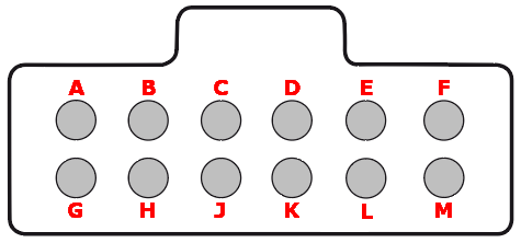
| Pin | Description | Note |
| A | +12V ignition coils power supply | Connect to a switched 12V source, 20A fused |
| B | Engine ground | Engine ground (if needed) |
| C | GPO 2 (fuel pump) | Ground output for relay control |
| D | GPO 6 (fan) | Ground output for relay control |
| E | GPO 3 | Ground output for relay control |
| F | Engine starter (+12V) | Put 12V on this wire from a switch or the ignition key crank position |
| G | +12V ECU power supply | Connect to a switched 12V source, 15A fused |
| H | GPO 8 / tacho | Selectable ground output with 5V or 12V pullup |
| J | GPO 15 (+12V) | Ground output for relay control |
| K | Motor 2 + (H-bridge output) | If not using E-throttle, can control an idle solenoid |
| L | Motor 2 - (H-bridge output) | If not using E-throttle, can control an idle solenoid |
| M | Alternator | Switched 12V in series with a charge light or resistor, see the ground section |
MaxxECU 16-pin connector. Pinout viewed from the wiring side of the extra connector, not the terminated harness:
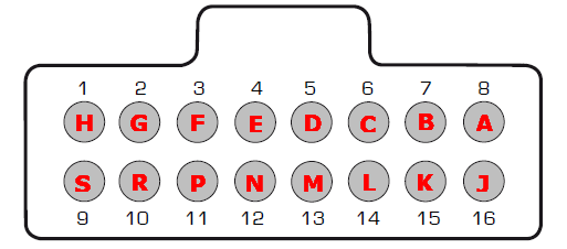
| Pin | Description | Note |
| 1 (H) | +5V power supply | Power supply for all 5V engine sensors |
| 2 (G) | Sensor ground | Ground for all engine sensors, NEVER connect to engine ground |
| 3 (F) | AIN 1 | Temperature input |
| 4 (E) | AIN 2 | Temperature input |
| 5 (D) | AIN 6, 0-5V analog input | Wrong marking on some harnesses! |
| 6 (C) | AIN 7, 0-5V analog input | Wrong marking on some harnesses! |
| 7 (B) | GPO 7 / DIN 3 | Ground output for relay control, or digital input |
| 8 (A) | GPO 5 | Ground output for relay control |
| 9 (S) | CAN L | To the chassis PT CAN pair, see the CAN section |
| 10 (R) | CAN H | To the chassis PT CAN pair, see the CAN section |
| 11 (P) | DIN 1 | Digital input |
| 12 (N) | DIN 2 | Digital input |
| 13 (M) | DIN 4 | Digital input |
| 14 (L) | DIN 5 | Digital input |
| 15 (K) | GPO 4 | Output |
| 16 (J) | - | Not used |
Summary of key GM E92 ECU pins. These are the main pins used on an LT swap with the E92/E92A ECU. The small-pin style for E92A connectors is Molex MX64, manufacturer part number 33468-0023, if you need to add terminals.
| Pin | Function | Notes |
| X1-14 / X1-33 | 5V pedal supply | BMW pedal pins 11 and 24 |
| X1-15 / X1-34 | Pedal position signals 1 and 2 | BMW pedal pins 20 and 7 |
| X1-30 / X1-53 | Pedal low reference (ground) | BMW pedal pins 10 and 23 |
| X1-51 | Run/crank ignition input | Connect to your keyed-on power wire |
| X1-52, X1-70, X1-73 | Constant battery positive | Main ECU power feeds |
| X1-59 | Cooling fan relay control | Triggers your fan controller or relay |
| X1-63 | Starter enable relay | Optional, for ECU-controlled start |
| X1-32 | AC compressor clutch relay | Drives the AC compressor when commanded |
| X1-6 / X1-21 / X1-22 | AC pressure sensor signal / 5V / low reference | Wire a GM 3-wire pressure transducer |
| X1-39 / X1-40 | CAN high / CAN low | Connect to the LT CAN box |
The BMW pedal pin numbers in the table above are N52/N54 numbers. The N55 equivalents are in the drive-by-wire section above.
The Full Guides
- Holley swap wiring information (the complete reference this tool summarizes)
- Holley wiring video walkthrough
- CAN box configuration and AC control
- Fan configuration
- Holley official: Terminator X / X Max LS installation and tuning manual (PDF) and the quick start manual (PDF)
- MaxxECU terminated harness install guide
- Fuel system page (EKP control)
- MaxxECU official: documentation hub, GM LS terminated harness page, and manuals and downloads
- Haltech official: Nexus Rebel LS installation and quick start guide
- LSe9x Haltech CAN box
- N55 equipped cars (all N55 chassis differences)


